The problem with the new design is that the vertical orientation of the RTL 510 can cause problems for tire clearance when mounted on the back of a Topeak rack when using my original mount, as shown in the photos below.


On this particular bike, it's possible to get the light into the original mount, but it touches the rear tire at the bottom, which is apparent in the side view. The actual tire clearance will depend on the size of the tires and the placement of the rack mount on the frame. On this bike, it touches with no room to spare, but I have the same Topeak rack on a different bike where there is at least 1 cm clearance to spare.

The new Varia requires an update to the design that moves the center of the Garmin mount vertically. The center channel of the Topeak rack poses a design constraint on how far vertically it can move, because that center channel is used for attaching various Topeak packs which slide in from the rear. So the light should not go higher than the center of that channel. It is possible to design a mount that would allow the mount itself to stay below that level, but the light would go above it slightly when installed. The second alternative is to keep the top of the light below that level so that packs could be installed or removed with the light in place. I chose for the second option, even though it does not allow quite as much additional clearance. To accomplish that, I moved the mount 1 cm vertically. In addition, I replaced my original 3-bolt mount with a 2-bolt deisng that only uses the center and top holes on the rack, as I believe 2 bolts are more than sufficient to keep the mount secure on the rack.

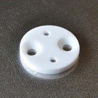
The mount installs similarly to the old design, with M3 nuts installed in the recesses, M5 angle-head bolts used to attach the bracket to the rack, and the M3 screws that come with the K-Edge bracket used to attach it to the adapter bracket.


I have already prototyped another variant of this design that allows the light to be moved an additional 1 cm vertically, but would require the light to be removed when installing or removing a bag.


Links:
Shapeways product page
Stumbled across this page and all the images are invalid.
ReplyDeleteThanks for pointing that out. It should be fixed now. Somehow the images were visible to me when logged in, but not to others.
DeleteHad a friend print this version for me; worked great!
ReplyDeleteDid you make the new version with more tire clearance? will it work for new 515 model?
ReplyDeleteThe screws that come with the K-Edge bracket are now too short to engage the hex nut. I had to buy tapered head M3 screws to secure the K-Edge bracket to the piece.
ReplyDeleteOtherwise seems to work. I'll be riding with it for the first time this weekend. Thanks for releasing the STL publically.
Thanks for that information. I could theoretically modify the design to bring the hex nuts closer, maybe by a millimeter. Do you think that would be enough for the supplied screws to work?
DeleteThe screw that comes with the K-Edge bracket is ~3.95mm from top to bottom. I can't easily measure how far it protrudes from out of the bracket, but it looks like ~1.7mm? I'm not sure how thin you could get the 3D printed bracket without compromising it. Might need threaded inserts?
DeleteFinding 6mm (iirc) M3 angle head bolts wasn't too hard (found some at the same place I goth the other bits). Added less than a dollar to the build cost. Everything worked out nicely on my ride in Galena.
This comment has been removed by the author.
ReplyDeleteI'm getting an invalid file error loading the original mount hex.scad. I can load the Garmin-Topeak-vert4.scad mount without error. Is there another site were I can download the original .scad file?
ReplyDeleteI use garmin with only radar, giving me plenty of tire clearance. The original mount has the advantage of my not needing to remove the garmin device to slide something on to the rack.
Thanks
I've gone and tested all of the links and they seem to be working for me. You want the .scad files and not the .stl files, right? If it's only the hex.scad file that's not working for you, I'll share the contents here as it's pretty short:
Deletemodule hex_prism(width, depth)
{
w2 = width/sqrt(3);
union() {
for(ang = [-60:60:60])
rotate([0, 0, ang])
translate([-w2/2, -width/2, 0])
cube([w2, width, depth]);
}
}
I appreciate your getting back to me. When I download OpenSCAD file 1 - The file that is downloaded is hex.scad I get an error when I try to open that file.
DeleteI can download and open OpenSCAD file 2 without any difficulity. Garmin-Topeak-vert4.scad is the name of the file that is downloaded.
I'm not sure what I am doing wrong.
The contents of OpenSCAD file 1 were basically a library function used by the second file. To simplify things I've consolidated them so there's only one download and I've edited the blog entry above to reflect that. Try the OpenSCAD file download and see if that works for you.
DeleteThis comment has been removed by the author.
DeleteThanks again. I figured it out. I was looking for the original T shaped design. I assumed file 1 was the original design and file 2 the new design. I went to the page with the original design and found the file for the T shaped design.
DeleteGood work. I have the same problem with clearance and I figured I’d mount the 515 horizontally and support it with a rear panel as the bouncing and vibration could cause it to come loose since the weight would be unevenly distributed. Your blog has given me some ideas. Thanks for posting this.
ReplyDelete