Showing posts with label 3D printing. Show all posts

Sunday, March 22, 2020

Updated mount for Garmin Varia RTL 510 on Topeak racks

In 2017, I wrote about the mount I had developed for attaching a Garmin Varia rearview radar to the existing mounting bracket on Topeak racks. That mount was designed with the original model, the Varia RTL 500, which is horizontally oriented. In 2018, Garmin updated the product with the Varia RTL 510. The new Varia offers various improvements on the original, such as a brighter light, and a vertical profile that is more functional when mounted on a seatpost.

The problem with the new design is that the vertical orientation of the RTL 510 can cause problems for tire clearance when mounted on the back of a Topeak rack when using my original mount, as shown in the photos below.


On this particular bike, it's possible to get the light into the original mount, but it touches the rear tire at the bottom, which is apparent in the side view. The actual tire clearance will depend on the size of the tires and the placement of the rack mount on the frame. On this bike, it touches with no room to spare, but I have the same Topeak rack on a different bike where there is at least 1 cm clearance to spare.


The new Varia requires an update to the design that moves the center of the Garmin mount vertically. The center channel of the Topeak rack poses a design constraint on how far vertically it can move, because that center channel is used for attaching various Topeak packs which slide in from the rear. So the light should not go higher than the center of that channel. It is possible to design a mount that would allow the mount itself to stay below that level, but the light would go above it slightly when installed. The second alternative is to keep the top of the light below that level so that packs could be installed or removed with the light in place. I chose for the second option, even though it does not allow quite as much additional clearance. To accomplish that, I moved the mount 1 cm vertically. In addition, I replaced my original 3-bolt mount with a 2-bolt deisng that only uses the center and top holes on the rack, as I believe 2 bolts are more than sufficient to keep the mount secure on the rack.

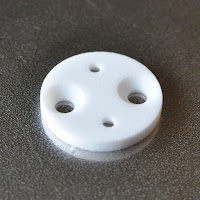

The mount installs similarly to the old design, with M3 nuts installed in the recesses, M5 angle-head bolts used to attach the bracket to the rack, and the M3 screws that come with the K-Edge bracket used to attach it to the adapter bracket.


With the new bracket installed, the RTL 510 now clears the tire on the bottom, with sufficient clearance on top to install rack bags with the light installed. It's not a lot of space, though. If I were going for a ride in the mud, I would probably put on my old RTL 500 even though its light is not quite as bright as the newer model.


I have already prototyped another variant of this design that allows the light to be moved an additional 1 cm vertically, but would require the light to be removed when installing or removing a bag.

Links:
Shapeways product page

Saturday, December 23, 2017

Pepper spray mounting bracket for bikes

Compared to the other places I've lived and biked extensively (Utah, Colorado, Missouri and Illinois), living in west Texas has had one unfortunate feature that the others mostly did not: unfenced dogs. I recognize that this occurs everywhere, but never with the frequency that I've experienced here. I have witnessed one situation where a dog ran into the road and took out a cyclist's front wheel, causing the rider to crash. I have witnessed multiple situations where a curious dog has run into the road because of a cyclist (usually me) and nearly into the path of a car. This has made it clear to me that the carelessness of these dog owners is posing a danger both to cyclists and also to the dogs themselves. I was initially reluctant to use pepper spray on dogs, but I've now concluded that this is the best solution for everyone. It's also clear to me that dogs learn quickly, as there is one particular dog that I see regularly and have sprayed once, who now stays put when I ride by.

With that introduction, I'm writing here to describe my new preferred solution for carrying pepper spray on rides: a mounting bracket that mounts underneath a water bottle cage, similar to many tire pump mounts. In fact, one of my bikes has the tire pump mount on one side of the water bottle and the pepper spray mount on the other side. This solution makes the pepper spray much more accessible when needed on short notice than a jersey pocket, for example.

I have bought multiple different brand pepper sprays, and they all have approximately the same dimensions. This bracket should work for any standard pepper spray, such as the one pictured below, which has a diameter of about 21 mm or 13/16 of an inch.


Like some of my other 3D printed projects, this bracket was designed using OpenSCAD. It works well for this type of design, though it's not necessarily suited to more complex designs. I got a prototype printed by Shapeways, and the first version looks like this:


Similar to many tire pump mounts, this mounting bracket has mounting holes that offer a certain amount of lateral adjustment in the placement, which allows the outer mount to be placed a range of distances from the down tube or seat tube of the bike. This is important because so many modern bikes, particularly those with carbon frames, have bigger diameter tubes in the down tube of the frame than in the past.

This picture shows the mounted bracket with a water bottle in the bottle cage.


Here is the bracket with pepper spray attached.


With the pepper spray in this position, it should be easily and quickly reachable by any rider accustomed to reaching down for a water bottle while riding. It has now been used for some off-road riding and has held the pepper spray securely so far. A bracket like this can be purchased from Shapeways via the product page I created.

3D-printed stem mount for Garmin

Last year I acquired a Garmin Edge 25. Garmin devices like it come with a handlebar mount, but they are less than ideal. The rubber O-rings that it uses to attach tend to break over time, and the mount tends to flex when buttons on the computer are pushed compared to the other available aftermarket mounts. I recently came up with my own design, which I had 3D printed in aluminum by Shapeways. This design is meant to attach to the top two stem bolts, and places the computer directly over the junction of the stem and handlebars. The bracket looks like this:


The bracket uses the Garmin mount inserts made by K-Edge (left), which can be purchased from their site for $5. The K-Edge insert comes with two M3 screws. The K-Edge mounts are threaded, but mine is not, so installation requires two M3 nuts (right) to be bought separately. These can generally be found at any hardware store.


The K-Edge insert attached to the stem mount looks like this.


Attaching the completed mount to the bike requires replacing the original stem bolts with longer ones.


This is the installed mount with a Garmin Edge 25 attached.


This version of the bracket is designed for a stem with bolts separated by 20 mm. I have created a product page on Shapeways for it. The design is easy to modify to accommodate other bolt spacings, and I hope to add other spacing options to the product page soon.

Sunday, March 26, 2017

Garmin Varia mount for Topeak racks

Last year I finally upgraded from the traditional style bike speedometer (with wires and magnets) I had been using for over a decade to a GPS-based computer, the Garmin Edge 25. Compared to the larger and more expensive ones, it's pretty basic, but it does the things I need, and it also supports external sensors. Over the winter I acquired my first external sensor: the Garmin Varia rearview radar. It allows a rider to monitor the location of vehicles approaching from behind within about 300 feet, and also functions as a tail light that gets brighter and blinks faster as cars approach. I really like it, and I think it's especially useful here in west Texas, where there are a lot of narrow roads with high speed limits, and enough wind to make it sometimes difficult to hear vehicles approaching from behind.

The Varia uses a Garmin quarter-turn mount, and comes with a seatpost version of the mount. Two of my bikes have Topeak rear luggage racks that seem to me better mount points for the Varia than the seatpost. The Topeak racks have a bracket on the rear for attaching a reflector (included with the rack) that looks like this:


This seems like an ideal mount point for the Varia, but of course nobody makes a Garmin mount that is designed to attach to something like that, so I designed one. The starting point for the design was the Garmin mount insert used by K-Edge:


K-Edge makes a number of different after-market mounts, all of which use the same plastic insert. I could have tried to replicate this myself, but as I've discovered from buying a less expensive after-market mount, a secure attachment requires getting the dimensions of the interface points right, and K-Edge have clearly already done so, so for $5 I can leverage their design and just focus on the interface with the Topeak rack. As shown in the picture, the insert comes with 2 M3 angle-head screws which are designed to screw into the metal mount. In this case, I needed a bracket that was thick enough to accommodate the screws and hold corresponding M3 nuts on the back side.

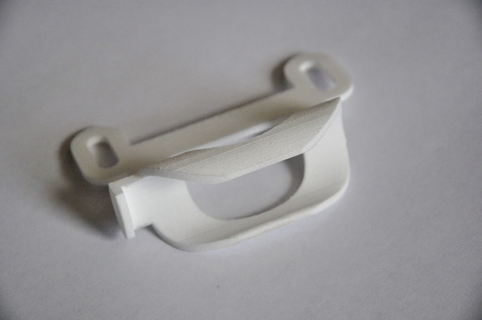
The design I came up with is this T-shaped bracket, which I had 3D printed by Shapeways.


It is 4 mm thick. The angled rack attachment holes are for angle-head M5 screws. To attach this to the rack requires 3 angle-head M5 screws and corresponding nuts. I used 12 mm screws and nylon-insert lock nuts, but plain nuts will probably work fine. Two M3 nuts are needed because they are not included with the K-Edge mount insert.


Bracket installation begins with inserting the M3 nuts into their corresponding recessed holes on the back of the bracket.


The bracket is then attached to the rack with the 3 bolts.


The K-Edge insert is attached to the bracket using the M3 screws. This is done after the bracket is already attached to the rack because the K-Edge insert slightly overlaps the top M5 screw.


At this point, the Varia can be attached.


Update (November 7, 2018):
One commenter noted that getting the design printed by Shapeways and shipped outside the US is quite expensive, so I'm also making my designs available for download. I am including an STL formatted file (a format readable by most 3D printers), as well as the original source code that I used to create the design in OpenSCAD.

STL file
OpenSCAD file

2020 Update:
I have created a new version of the design that uses less material, fewer screws to attach, and works better with the new RTL 510 and RTL 515 radar designs from Garmin.

Wednesday, September 21, 2016

3D printed cable guide for X-Peria tandem fork

In my original entry about the X-Peria tandem, I noted that the fork did not have an obvious method for routing the cable to the disc brake, but that there was a screw hole on the inside of the left fork blade. My solution was a 3D-printed bracket designed to attach to the screw hole and reach around behind the fork blade where the cable would pass through it.

I used OpenSCAD, a free CAD software to create the design. This is an OpenSCAD rendering:


Note that the hole for the screw mount has a flared shape to accommodate an angle-head screw, so as to minimize the amount the screw protrudes into the space inside the fork. The OpenSCAD source code for this design is below:

guidelength = 20;
width = 15;
cablesize = 5;
thickness = 1.5;
screwhole = 5;
len1 = 5;
len2 = 5;
th2 = 2.5;
angle = 70;
bendradius = 10;

$fs=0.01;
$fa=3;

r2 = screwhole/2+4;
cr = cablesize/2;
ofs = width/2-r2;
d = (guidelength-width)/2;

rotate(angle) {
difference () {
    union () {
        // cable guide outer
        translate([0, 0, -d]) cylinder(guidelength, r=cr+thickness);

        // connector section 1
        translate([0, -th2/2, 0]) cube([len1, th2, width]);

        // connector bend
        translate([len1, -th2/2-bendradius, 0]) rotate([0, 0, 90])
        rotate_extrude(angle=-angle) {
            translate([bendradius, 0, 0]) square([th2, width]);
        }
    }

    // cable guide hole
    translate([0, 0, -d-0.01]) cylinder(guidelength+0.02, r=cr);
}


// connector section 2
translate([len1, -bendradius-th2/2, 0]) rotate([0, 0, -angle])
translate([len2, bendradius+th2/2, width/2]) rotate([90, 0, 0])
translate([0, 0, -th2/2])
    difference() {
        hull() {
            cylinder(th2, r=r2);
            translate([-len2/2, -ofs, 0]) cylinder(th2, r=r2);
            translate([-len2/2, ofs, 0]) cylinder(th2, r=r2);
            translate([-len2-1, -width/2, 0]) cube([1, width, th2]);
        }
        translate([-len2-r2, -width/2-0.05, -0.05]) cube([r2, width+0.1, th2+0.1]);

        // Screw hole
        translate([0, 0, -0.05]) cylinder(th2+0.1, r=screwhole/2);

        // flared hold for angle head screw
        translate([0, 0, -1]) cylinder(screwhole/2, screwhole, screwhole/2);
    }
} 

The part was printed in white ABS plastic by Shapeways. I have produced other parts using Shapeways before and have found the results to be very high quality. A couple of weeks after placing my order, the cable guide arrived.


The hole for the cable was actually just a little too tight for the cable to fit, so I widened it slightly with a drill. This is actually the second version of the design, the result of some changes I made to my first design after I had a chance to test it on the bike. Here is the final product, installed on the bike.